

More displacement and greater leverage means more torque. This concept is obvious when you compare the torque ratings between factory small block motors and factory big block motors. However, nowadays it is not necessary to suffer the time and switching costs of leaping to a larger block if you are only after more displacement. Displacement is just a factor of bore and stroke, by increasing the stroke of your current motor Formula A. Displacement. Simply a factor of bore and stroke. Increase the stroke of your current motor and reap the benefits of more torque.
you can enjoy the satisfaction of more torque disguised in the same package.
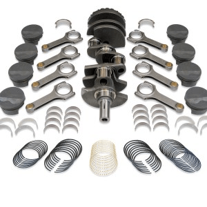
Widespread awareness of the facts above and an abundance of aftermarket stroker kits have made the stroker option extremely popular. If you are out for performance, a stroker is a wise alternative to building a motor that only meets the factory displacement. Whether you have already built a stroker motor or are simply researching them, take a little time to learn the basics and understand the benefits and possible compromises of the now popular engine building practice.
Stroker Motor (def.)
A motor that has greater than stock displacement due to an increase in the factory crank throw. An increase in crank throw increases stroke (the difference between the piston’s top dead center and bottom dead center position).
The illustrations below show the difference between a stock and a stroked rotating assembly. Study the differences and you can see what makes up a typical stroker motor. Though a bit exaggerated for effect, the stroked cross section in Figure 2 incorporates:
Increased Crank Throw (distance between C and D)
Increased Rod Length (distance between B and C)
Decreased Piston Compression Height (distance between A and B)
Keep in mind that rod length does not affect the displacement of the engine, it is common to have a stroker motor that uses an increased crank throw, decreased piston compression height, and stock rod length to achieve additional stroke. We’ll discuss why longer rods are often used in stroker motors later in the article.
The animation below helps visualize the effect of increased stroke and rod length on piston travel and speed.
Stroker Evolution
Stroker engines are nothing new, and in fact they are not even an aftermarket invention. If you look closely at factory engine offerings, you’ll see that changes in displacement are often nothing more than a change in stroke. This was a cost effective way for the factory to increase power for larger vehicles, or future models, while reusing the same block and accessory components.
Performance enthusiasts then caught on and they found that creative machining and parts matching could yield more cubes while hidden in the stock block to fool fellow racers.
One of the methods used to increase stroke with a stock crank, is called offset grinding. By offset grinding the rod journal you move the centerline of the rod journal away from or toward the centerline of the main journal. This will result in increased or decreased stroke. Figure 3 above illustrates the case we are interested in, the rod journal is ground in a manner to increase stroke. Keep in mind that when the rod journal is offset ground it now has a smaller diameter. The motor will require special connecting rods with correctly sized bearing bores. Additionally, if the rod journal is ground too much it becomes weak. Unless you add material and regrind, you can only stroke a motor so far with a stock crank.
Due to a demand for more stroke than offset grinding a stock crank could achieve, many aftermarket companies developed specialized cast and forged cranks with relocated rod journals. The specialized stroker crank has dramatically increased the amount of stroke you can add to your stock bottom end. Stroker cranks require a shorter piston to keep the factory sized piston from extending beyond the deck surface, it is also shortened to accommodate a longer rod. In the past the only way to complete a stroker motor was to find the right combination of rod lengths and piston heights. This often meant researching other factory motors for the right dimensions. It was not uncommon to have a Small Block Ford stroker motor consisting of Pinto rods and Chevy pistons.
Longer rods are often required to increase leverage and minimize the high degree of rod angularity created by the increase in stroke. The longer rod also prevents the piston from being pulled out the bottom of the cylinder bore. Rod Ratio and rod angularity are especially important issues to consider before simply choosing the stroker kit that yields the largest displacement for your application. We will discuss these topics in the following section.
Rod Ratio (Rod to Stroke Ratio)
Rod Ratio or Rod to Stroke Ratio is the figure achieved when dividing a motor’s rod length by its’ stroke. This is an important calculation to understand since it informs us about a motor’s rod angularity. A low Rod Ratio yields a high rod angle. For example, a motor with a 5.400″ rod length and a 3.000″ stroke yields a rod ratio of 1.8:1. If we maintain the same stroke and shorten the rod length to 5.000″ we get a 1.7:1 rod ratio. The rod angle has increased.
A high rod angle or low Rod Ratio creates a greater potential for accelerated wear to cylinder walls, pistons, and piston rings. The illustrations below show why this is so. Figure 5 is exaggerated for effect but clearly shows how an extremely low Rod Ratio can drive the piston into the side of the cylinder wall.
Figure on the right is a Low Rod Angle. (High Rod Ratio)
Figure on the left is a High Rod Angle. (Low Rod Ratio)
By lengthening the rod, as stroke is increased, we can offset the increased rod angle. However, this requires further shortening of the piston. The further the piston is shortened the more likely the piston pin will intersect the oil ring groove, creating a potential for increased oil consumption.
“Shortened Piston. The further the piston is shortened the more likely the piston pin will intersect the oil ring groove.”
Many piston companies however have engineered pistons to avoid this problem with tighter ring packs and bridge rings. Either way, there comes a point when you cannot shorten the piston any further before dependability is compromised. As in the discussion about offset grinding, we have reached a limit to how far you can stroke a motor before some component or function is sacrificed.
The consensus amongst engine manufacturers is that a ratio of 1.50″ is the lowest acceptable rod ratio for a street motor. Realistically, rod ratios between 1.65″ – 1.80″ are ideal. See the tables in the following section about stroker kits. Notice how the Rod Ratio decreases as stroker displacement increases.
Piston Dwell Time and Piston Speed
An often overlooked factor that contributes to the advantage of a stroker motor has to do with piston dwell time, the amount of time the piston remains at the top and bottom of the stroke. The increased stroke and rod length of a stroker motor yields a longer piston dwell time. Longer dwell time allows for better flow of combustion and exhaust gases since the piston accelerates slower in the transition between “up” and “down” strokes. Intake gases have a longer time to enter the cylinder while exhaust gases are given more time to escape. This translates into more natural torque over a longer range of rpm. Power and torque can also be enhanced with valve event timing and cam profile.
Even though the piston accelerates slower in transition, the piston ultimately reaches higher speeds to cover the additional stroke. This increase in piston speed means greater component strain. Another factor to consider before simply going with the kit or components that give you largest stroke increase.
Stroker Building Considerations
As you may have guessed, there are certain issues which must be addressed when actually assembling any stroker engine. First and foremost is the issue of clearances. Due to the increased stroke and rod length changes, it is common for the rod and crank to interfere with cylinder bore end, pan rails, piston skirts, windage trays and other areas inside the block. Therefore it is mandatory that you preassemble the engine components, mark the areas needing grinding for clearance, disassemble and make the necessary clearances, and then reassemble and check again. As a rule of thumb you should have at least 0.030″ clearance between any interfering points. Another set of considerations unique to stroker engines is rotating assembly balancing. Whether the stroker kit is custom made, or off-the-shelf, the use of new or offset ground cranks, longer rods, and stroker specific pistons ensures that the assembly is not going to spin evenly. Any stroker kit, even off-the-shelf ones, must be balanced by a competent machine shop. Not doing so is a recipe for failure. Always perform the balancing with the harmonic balancer and flywheel you intend to use.
Stroker Kits
Many of the issues that arise when planning a stroker motor are solved by using a kit that provides a crank, connecting rods, and pistons. Rather than purchasing the components separately, you can purchase predetermined safe combinations for your block. You will get a thousand differing opinions regarding the best stroker for your application. We urge you to gather opinions from fellow enthusiasts and engine builders. Also use the information about rod angularity in this article to make your decision. Stroker displacements remain fairly consistent from kit provider to kit provider. We have highlighted the most popular stroker displacements for Ford blocks in the tables below.
289-302 based strokers (4.030″ bore – 0.030″ over stock)
Displacement 289 302 315 331 347 355
Rod Length 5.155″ 5.090″ 5.205″ 5.400″ 5.400″ 5.205″
Stroke 2.870″ 3.000″ 3.076″ 3.250″ 3.400″ 3.500″
Rod Ratio 1.796:1 1.696:1 1.692:1 1.662:1 1.588:1 1.487:1
351W based strokers (4.030″ bore – 0.030″ over stock)
Displacement Stock
351W 383 393 408 418 426
Rod Length 5.956″ 6.250″ 5.956″ 6.125″ 6.200″ 6.125″
Stroke 3.500″ 3.750″ 3.850″ 4.000″ 4.100″ 4.170″
Rod Ratio 1.702:1 1.667:1 1.547:1 1.531:1 1.512:1 1.469:1
351C based strokers (4.030″ bore – 0.030″ over stock)
Displacement Stock
351C 383 396 408 426 –
Rod Length 5.778″ 5.850″ 6.000″ 6.000″ 6.000″ –
Stroke 3.500″ 3.750″ 3.850″ 4.000″ 4.170″ –
Rod Ratio 1.651:1 1.560:1 1.558:1 1.500:1 1.44:1 –
429 and 460 based strokers (4.440″ bore – 0.080″ over stock)
Displacement Stock
429 Stock
460 501 532 557 –
Rod Length 6.605″ 6.605″ 6.800″ 6.800″ 6.800″ –
Stroke 3.550″ 3.850″ 4.150″ 4.300″ 4.440″ –
Rod Ratio 1.861:1 1.715:1 1.638:1 1.581:1 1.531:1 –
In reality there are many more displacements possible for the blocks above if you decide a kit does not meet your needs.
This does however require a greater understanding of custom engine building and that is where you friends at Bessel Motorsports and www.Strokerkits.com can help you out. Call them today and speak with one of super tech reps for all of your stroker questions 636-946-4747 or email them direct at sales@strokerkits.com.
Tell them your buddy over at Greaser Alley sent you & maybe they will give you a discount.

Good info site thanks
LikeLike